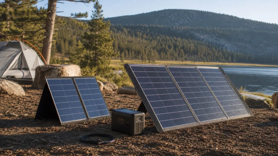
For eight hours per day, a first-pass panel range is about 50-100W for Starlink Mini, 125-190W for Standard Actuated, 190-255W for Standard 4/4 X, and 280-380W for Performance. For continuous 24-hour operation, those ranges triple. These figures assume 4.5 good-sun hours, the Starlink calculator’s default 70% solar-delivery setting, no separate network gear, and a power station that can accept the full array.
That 70% is a planning allowance in the calculator, not a measured efficiency for every panel, station, or weather condition. Size from measured energy and local conditions whenever uptime matters.
Current model ranges and calculated panel watts
Starlink’s current power support page lists average AC input ranges of 20-40W for Mini, 50-75W for Standard Actuated, 75-100W for Standard 4/4 X and Enterprise, and 110-150W for Performance Gen 1 and Gen 2. Starlink says those figures include the terminal, included Wi-Fi router, power supply, and cables.
Using the published endpoints, 4.5 good-sun hours, and a 70% planning factor:
| Starlink hardware | Panel for an 8-hour session | Panel for 24-hour daily use |
|---|---|---|
| Mini, 20-40W | 51-102W | 152-305W |
| Standard Actuated, 50-75W | 127-190W | 381-571W |
| Standard 4 / 4 X / Enterprise, 75-100W | 190-254W | 571-762W |
| Performance, 110-150W | 279-381W | 838-1,143W |
These are calculated panel nameplate watts, rounded to the nearest watt. They are not product recommendations or cloudy-weather guarantees.
The formula behind the table
Starlink session energy (Wh)
  = (internet setup watts + extra router or Wi-Fi watts) x hours needed

Panel rating needed (W)
  = session energy / (good sun hours x planning efficiency)
Example for a Standard 4 setup averaging 85W for eight hours, with no separate router:
Session energy = 85W x 8h = 680Wh
Panel rating = 680Wh / (4.5h x 0.70) = 216W
A nominal 200W panel produces 630Wh in that same planning scenario:
200W x 4.5h x 0.70 = 630WhIt would cover an eight-hour session near the low end of the 75-100W Standard 4 range, but not the 85W example or the published high end. There is also no weather reserve in that calculation.
Use the Starlink calculator exactly as built
The Starlink power station runtime calculator asks for:
- Internet setup watts
- Extra router or Wi-Fi watts
- Power station capacity
- Usable battery percent
- Hours needed
- Good sun hours
- Solar energy delivered
Its panel result uses internet setup watts, extra watts, hours needed, good-sun hours, and the entered solar-energy-delivered percentage. Capacity and usable battery percent determine battery runtime and required capacity; they do not change the energy that Starlink consumes during the selected session.
Because Starlink’s published ranges already include its router, put only a separate mesh node, third-party router, switch, or other added network gear in Extra router or Wi-Fi watts.
Replace the energy used, not automatically the whole battery
If Starlink uses 680Wh during a session, the repeatable solar target is at least that 680Wh plus the losses represented by your planning factor. A 2,000Wh battery does not require 2,000Wh of solar every day if only 680Wh was removed.
Use the solar recharge time calculator when you specifically want to model a battery refill. It asks for:
- Power station capacity
- Panel rating
- Power station solar input limit
- Good sun hours per day
- Real-world efficiency
- Starting battery level
The Starlink calculator sizes panels directly from the selected internet session and its Solar energy delivered setting. The recharge-time tool instead models how long a specified panel takes to refill a battery of a stated capacity and starting level.
Choose realistic good-sun hours
Good-sun hours are equivalent full-output hours, not hours between sunrise and sunset. Solar resource changes with location, season, orientation, shade, clouds, and temperature. The Department of Energy’s PV performance guidance explains that panel ratings use 1,000 W/m2 irradiance and 25 C cell temperature, conditions that do not persist all day.
NLR’s current PVWatts model uses long-term weather data and reports prediction uncertainty. PVWatts models fixed grid-connected arrays, so use it as location and seasonal context rather than a promise for a movable folding panel. Shade at the actual deployment spot can dominate the result.
Run at least three scenarios:
- A favorable clear-sun day
- A normal seasonal day
- A poor-weather or partially shaded day
If the plan works only in the favorable case, the battery will lose state of charge over repeated days whenever production falls short of consumption.
The power station input can make the panel target impossible
The station must be able to accept the array you calculated. Verify:
- Maximum solar input watts
- PV operating voltage range
- Cold-adjusted array open-circuit voltage (
Voc) - Operating and short-circuit current limits, as specified by the station
- Connector, keyed variant, polarity, and cable rating
- Permitted series or parallel configuration
If a station accepts 500W maximum, adding 800W of panels does not give the calculator an 800W charging path. Whether the manufacturer permits that amount of panel oversizing at all depends on the station’s voltage, current, short-circuit, and array rules.
Use the solar panel compatibility checker for a maximum-spec screen and the full compatibility guide for minimum voltage, Vmp, Isc, cold Voc, wiring, connector, polarity, and controller checks.
Do not add a controller by assumption
Some panel kits include a PWM or MPPT controller for charging a bare battery. A power station’s solar input is a different charging path. Use the panel output and cable identified by the station manual, and do not insert a kit controller, bypass regulated electronics, or feed a USB/DC output into the PV input unless the manuals explicitly allow it.
For a concrete example of why manual limits matter, EcoFlow’s current DELTA 2 manual specifies an 11-60V, 15A, 500W solar input. Those three limits still apply if a physically compatible adapter can be found.
Battery and operating checks still matter
Solar sized for daily energy does not guarantee overnight service. The battery must carry the no-sun period and poor-weather reserve. Also confirm that the station:
- Supports charging while powering the selected outputs in the intended mode
- Does not turn the AC or DC output off under the Starlink load
- Can remain within its charging and discharging temperature limits
- Recovers as expected after low battery, overload, or loss of solar input
Test the full setup over a representative day before treating it as outage or remote-work infrastructure. For the battery side of the design, use the Starlink power station sizing guide.