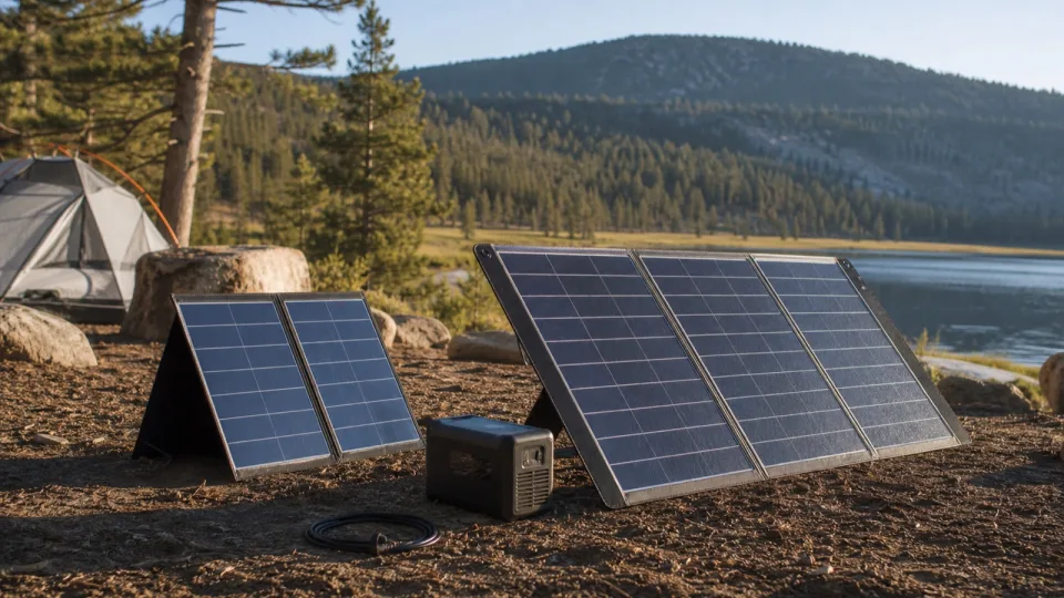
A solar panel works with a power station only when the complete array stays inside the station’s PV voltage, current, and watt limits and uses the correct cable and polarity. The panel’s brand and headline wattage are not enough. Maximum voltage is the hard stop; minimum operating voltage, current, connectors, and the intended charging path also matter.
Use the station and panel manuals for the exact model numbers. Specifications can change between generations that share a product name.
Collect these specifications first
From the power station manual, record:
- Solar or PV operating voltage range
- Absolute maximum PV open-circuit voltage, if listed separately
- Maximum input current
- Maximum PV short-circuit current, if listed
- Maximum solar input watts
- Solar input connector, polarity, and required cable
- Allowed series or parallel panel configurations
From the panel label or manual, record:
- Rated maximum power (
Pmax) - Open-circuit voltage (
Voc) - Voltage at maximum power (
Vmp) - Short-circuit current (
Isc) - Current at maximum power (
Imp) Voctemperature coefficient- Output connector and polarity
Do not use the marketing term “12V panel” in place of those values. It describes a product class, not the panel’s actual operating or open-circuit voltage.
Check maximum voltage in cold conditions
The array’s cold-adjusted Voc must remain below the station’s maximum PV voltage. Victron’s MPPT installation manual specifically requires both Voc and its temperature coefficient when sizing a series array, because Voc rises below 25 C.
When the panel data sheet gives a negative Voc coefficient in percent per degree C, a planning calculation is:
Cold Voc
  = nameplate Voc x [1 + (absolute coefficient / 100)
    x (25 C - lowest design temperature)]
For a series string, use the sum of every panel’s Voc before applying or summing the temperature adjustment as directed by the manufacturer.
Hypothetical example:
Panel Voc: 24.3V
Voc coefficient: -0.28% per C
Lowest design temperature: -10 C

Cold Voc = 24.3 x [1 + 0.0028 x (25 - -10)]
         = 26.7V
That example fits below a 30V maximum, but it does not create a universal safety margin. If the panel omits the coefficient or the station manual does not define its voltage limit clearly, ask the manufacturer rather than inventing a percentage buffer.
Check the operating voltage range
Vmp is the panel voltage near its rated maximum-power point. It needs to fall within the station’s documented operating or MPPT range under the conditions in which you expect to charge.
A panel can be below the maximum Voc limit yet still fail to charge because its operating voltage is below the station’s startup or minimum MPPT voltage. Conversely, a panel that starts charging in warm sun can exceed the maximum Voc on a cold clear morning if the array was sized too closely to the limit.
Check current and watt limits separately
Compare Imp with the station’s operating-current limit. If the station also specifies a maximum PV short-circuit current, compare array Isc with that separate limit.
Do not assume every station treats excess current or panel wattage the same way. Some manuals permit an oversized array and cap what the controller draws; others prescribe specific array limits. Follow the station’s language. A watt limit does not override voltage or current restrictions.
One current manufacturer example shows all three limits together: the EcoFlow DELTA 2 manual specifies 11-60V, 15A maximum, and 500W maximum for solar charging. A panel must satisfy the applicable limits, not merely stay below 500W.
Recalculate the array when using multiple panels
For matched panels wired in series:
Array Voc = panel Voc x number of panels
Array Vmp = panel Vmp x number of panels
Array Imp is approximately one panel's Imp
Array Isc is approximately one panel's Isc
For matched panels wired in parallel:
Array Voc is approximately one panel's Voc
Array Vmp is approximately one panel's Vmp
Array Imp = panel Imp x number of parallel panels
Array Isc = panel Isc x number of parallel panels
Series wiring raises voltage; parallel wiring raises current. Mixed panel models, partial shade, branch fusing, cable sizing, and more complex series-parallel arrays need model-specific design rather than these screening formulas. Use only configurations allowed by both manufacturers.
Match the connector, polarity, and cable
The panel-side and station-side connectors are separate questions. A rigid or portable panel may use PV connectors, while the station may require a model-specific barrel, high-power, or keyed charging connector. Even plugs that look alike can differ in dimensions, pin assignment, or polarity.
An adapter does only this:
physical connector A -> physical connector BIt does not lower Voc, limit current, correct polarity, or make an unsupported array safe. Confirm the adapter’s voltage and current rating and trace positive to positive before connection. EcoFlow’s portable-panel manual tells users connecting to a third-party device to confirm that it accepts solar input and that its ports and electrical parameters match.
Do not guess where a charge controller belongs
Portable panel kits can expose different kinds of output:
- Raw panel output intended for a station’s PV input
- A regulated USB or DC output
- A separate PWM or MPPT controller intended to charge a bare battery
A power station’s PV input is not the same thing as a bare 12V battery terminal. Use the panel output and cable named in the station manual. Do not place a kit controller between panel and station, bypass one, or feed a regulated output into the PV port unless both manuals explicitly support that path.
This is also why the phrase “built-in controller” needs context. Identify which device controls which charging path instead of assuming more controllers are better.
Use the compatibility checker for its actual scope
The solar panel compatibility checker asks for exactly:
- Panel or array watts
- Panel or array Vmp
- Panel or array Voc
- Panel or array Imp
- Cold-weather Voc allowance percent
- Station minimum input volts
- Station maximum input volts
- Station maximum input amps
- Station maximum input watts
The checker calculates cold-adjusted Voc = entered Voc x (1 + allowance / 100), verifies that Voc is not below Vmp, and screens Vmp, cold-adjusted Voc, Imp, and rated watts against the entered station limits. The allowance is an input, not a universal recommendation; use the panel coefficient and expected low temperature when available.
It does not ask for panel Isc, a separate station short-circuit-current limit, the actual temperature coefficient or design temperature, connector, polarity, cable rating, controller path, or every manufacturer restriction. Complete those checks manually before buying or connecting equipment.
After compatibility is established, use the solar recharge time calculator to estimate charging time. The 100W vs 200W panel guide explains when additional compatible wattage actually shortens the refill.
Final pre-connection checklist
- Exact station and panel model manuals match the equipment in front of me.
- Cold-adjusted array
Vocremains below the station maximum. - Array
Vmpfits the station’s startup and operating range. - Array
ImpandIsccomply with the applicable current limits. - Array watts comply with the manufacturer’s allowed configuration.
- Connector, polarity, and cable ratings are confirmed.
- The selected panel output follows the station’s approved controller path.
- Series or parallel math covers the entire connected array.
If any box is unknown, leave the panel disconnected until the manufacturer or a qualified installer resolves it.