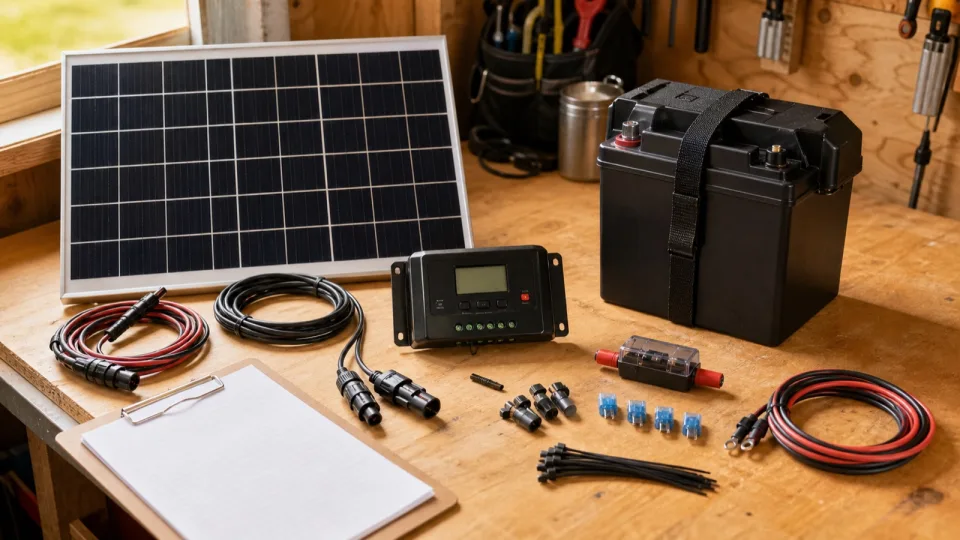
A starter 12V solar kit needs more than a panel and a controller with matching brand colors. Before buying, verify the complete path:
sun -> panel -> protection/disconnect -> charge controller
    -> protected battery circuit -> battery -> protected loads or inverter
This is a pre-purchase compatibility checklist, not installation instructions. DC batteries can supply destructive fault current, and rules differ by location and application. Use the exact equipment manuals and qualified local help for the finished installation.
Start with daily load energy
List every intended load before choosing the panel:
Daily load energy (Wh) = load watts x hours per dayFor several loads, calculate each row and add the Wh. If a label provides amps instead of watts, use the device’s specified operating voltage and W = V x A, or measure the load.
The 12V shed-lighting calculator turns light watts, nightly hours, backup days, battery voltage, and sun hours into an initial battery and panel target.
Worked energy screen
Assume three 5W DC lights run five hours per night:
Daily load = 15W x 5h = 75Wh/day
Two no-charge days = 75Wh x 2 = 150Wh
Battery target at 80% planned use = 150Wh / 0.80 = 188Wh
Battery Ah at 12.8V = 188Wh / 12.8V = 14.7Ah
For daily solar replacement, assume four good-sun hours and 70 percent end-to-end delivery:
Panel screen = 75Wh / (4h x 0.70) = 27WThat does not make a 30W panel and 15Ah battery a finished design. The assumptions omit extended cloudy weather, snow or dust, future loads, controller self-consumption, conductor loss details, temperature effects, product-specific limits, and installation requirements. Run less favorable scenarios before selecting hardware.
Use the Ah-to-Wh calculator whenever a battery listing gives capacity only in amp-hours.
1. Solar panel data to collect
The panel data sheet should identify:
- Maximum power (
Pmax) - Open-circuit voltage (
Voc) - Voltage at maximum power (
Vmp) - Short-circuit current (
Isc) - Current at maximum power (
Imp) - Temperature coefficient for
Voc - Connector type and polarity
- Dimensions, weight, mounting points, and environmental rating
Panel watts alone cannot establish controller compatibility. Series wiring adds voltage; parallel wiring adds current. In cold conditions, Voc rises, so the controller’s maximum PV voltage check must use the array’s cold-adjusted value.
The Department of Energy explains that PV output depends on light and cell temperature. Treat panel nameplate watts as a test-condition rating, not energy guaranteed every sunny-looking hour.
2. Charge-controller limits to match
Get the exact controller model and manual. Verify:
- Supported battery-system voltage
- Supported battery chemistries and configurable charge settings
- Maximum PV open-circuit voltage
- PV operating or startup voltage requirements
- Maximum PV current and power for the battery voltage
- Maximum battery charge current
- Temperature sensing or compensation requirements
- Load-terminal current and behavior, if loads will use those terminals
- Required cable sizes, terminal torque, fuses, disconnects, and connection order
Do not transfer limits from one controller to another. For example, the current Victron SmartSolar MPPT 100/30 and 100/50 manual says its array must not exceed 100V open circuit, nominal PV voltage should be at least 5V above battery voltage, cold Voc must be considered, and the battery should normally be connected before PV so system voltage is detected. Those are useful examples of the checks a real manual contains, not generic settings for every controller.
3. Battery specifications to verify
Record:
- Nominal voltage and nameplate Wh or Ah
- Battery chemistry
- Manufacturer-approved charge voltage and current
- Continuous and peak discharge-current limits
- Battery-management-system cutoff and recovery behavior
- Charge and discharge temperature limits
- Low-temperature charge protection, if applicable
- Series or parallel connection rules
- Required fuse, conductor, terminal torque, enclosure, and mounting orientation
- Warranty conditions
The controller’s battery preset is not enough evidence by itself. Compare the actual charge stages and voltages with the battery manual. If the two manufacturers’ instructions cannot be reconciled, choose a documented combination or get qualified design help.
4. Wire, fuse, disconnect, and fault-current details
A kit that lists only cable length and connector type is incomplete for design review. You need conductor material, gauge or cross-sectional area, insulation temperature and voltage rating, length, routing conditions, terminal compatibility, and expected current.
Protection must be coordinated with the conductor and equipment, not selected from battery Wh. Victron’s current technical guidance notes that batteries can supply very high current and that battery conductors need appropriate fusing. Its Wiring Unlimited reference also covers voltage drop, interrupt rating, fuse selection, disconnects, battery-bank wiring, and grounding.
Check whether the kit actually includes:
- Battery-side overcurrent protection
- PV-side protection or disconnect where required
- Properly rated lugs, connectors, and strain relief
- A battery enclosure or terminal covers
- Busbars or distribution hardware when multiple circuits are used
- Grounding and bonding parts required for the installation
- Mounting hardware suitable for the roof, pole, wall, or portable frame
Do not assume an automotive fuse, AC breaker, unknown marketplace cable, or connector adapter is suitable for the available DC fault current.
5. Decide whether loads are DC or AC
Running 12V DC lights from a protected DC circuit is a different design from adding a 120V inverter.
If an inverter is included, verify:
- Continuous and startup output
- DC input-current demand at full load
- Low-voltage cutoff
- No-load or standby consumption
- Waveform and equipment compatibility
- Grounding, neutral, transfer, and receptacle requirements for the intended use
- Cable and fuse requirements in the inverter manual
An inverter can dominate a small system’s current and idle energy. Add it only when the actual loads require AC.
6. Check what the kit leaves out
Renogy’s current 100W starter-kit documentation is a useful reminder to inspect the data sheet and user manual for a named kit rather than relying on the phrase “starter kit.” Make a priced bill of materials from the documents.
Common missing or underspecified items include:
- Battery
- Correct battery-to-controller cable and protection
- Load distribution and branch protection
- Roof or pole mounting parts
- Weatherproof cable entries and enclosures
- Longer cable runs and the larger conductor they may require
- Monitoring or a battery shunt
- Low-temperature battery protection
- A controller sized for a future second panel
The lowest kit price is not the finished-system price.
Red flags before purchase
- No exact controller model or downloadable manual
- Panel watts listed without
Voc,Vmp,Isc, andImp - No battery charge profile or configurable voltage information
- No conductor gauge, material, or length
- Fuse included but no type, rating, interrupt capability, or placement documentation
- “Works with 12V batteries” without chemistry and charge-setting details
- Product photos show components the included-parts list does not name
- Promised daily energy with no location, season, shade, orientation, or loss assumptions
Final pre-purchase sequence
- Calculate daily Wh and backup days from real loads.
- Convert the battery label from Ah to Wh when needed.
- Run favorable, normal, and poor-solar scenarios.
- Match panel cold
Voc, operating voltage, current, and power to the controller manual. - Match controller charge behavior to the battery manual.
- Build the complete conductor, protection, disconnect, mounting, and enclosure list.
- Check every load and any inverter against battery and controller current limits.
- Have the final design reviewed for the installation type and local requirements.
Next action: enter the actual lighting load in the 12V shed-lighting calculator, then create a line-by-line bill of materials from the panel, controller, battery, and load manuals before comparing kit prices.